Influence from fittings and connectors on your mould cooling behaviour
04.2021 | 8 min
By Csaba Csipke
Introduction
Do we pay enough attention to tempering?
Although tempering plays an important role in the injection moulding technology, the number of monitoring system in the manufacturing plants is insignificant. The injection moulding companies usually rely on the machine data during the injection moulding and tempering process. In most cases mould tempering based on the feedback of the tempering device without a validation process. To understand the tempering process, it is not enough to rely on the data displayed on the controller. The surface temperature of the (forming part of the) mould and the set water temperature depends on many factors, so to control and monitor them becomes more necessary. The difference between tempering devices, the high number of water circles, the length and size of the hoses, the used connectors, collectors, and manifolds can bring uncertainty factor into the tempering process, therefore change the heat balance of the mould.
The life span of the mould easily can be 5-10 years, during that time they require maintenance. The water flowing in the mould often behaves aggressively towards metals and causes undesired corrosion. The water quality greatly affects the appearance time and size of deposits in the water circuits, but in general it can be said that the water circuits need to be cleaned. Even 1 mm thick limescale can reduce the heat transfer by 6%.
Monitoring systems provide an immediate solution in identifying unexpected errors. A slipped connector, a not started tempering device or an inversely connected hose can be immediately detected. During mass production a cyclically broken hose, or the failed connection of a self-locking connector can cause great change in the water volume, and its identification takes a lot of time.
When starting production with a new injection mould it is recommended to record not only parameters of the injection moulding technology, but the tempering data too. It can be the required water connection arrangement to produce the part, identification of the used tempering device, or the water volume and temperature. These can guarantee the constant product quality and stable process for subsequent production.
Beside the water temperature, the flow volume plays an important role in mould tempering. Without monitoring, we cannot be sure if the different tempering devices operate with the same values. In practice significant differences can develop between tempering device over time. The regular monitoring of the pump characteristic is a solution to check this. It is also recommended to perform measurements after mould maintenance to verify water permeability.
With our measurement we want to show the importance to establish, maintain a suitable tempering environment and to continuously test it. Often significant difference can occur between two identical tempering devices, we will examine these and prove the flow reducing effect of the quick connector. Tempering control gives a solution to detect errors, which can refer to the change of the tempering device condition, to incorrectly connected hose, or even to an inadequate setting. These changes are hardly or not detectable without control system.
Used materials and equipment
Tempering device:
During the measurement we used two identical tempering devices, their type is Wittmann Tempro Basic C91 (Table 1). Their year of manufacturing is same, but their operating time is different, therefore their efficiency is different too. The operating temperature of the tempering devices is set to 35°C.
Table 1. Main technical data of Wittman Tempro Basic C90 type tempering device
|
Heating output |
kW |
9 |
|
Pumping capacity |
l/min, |
40 |
|
bar |
3,8 |
|
|
Cooling water connections |
Col |
1/4 |
|
Tool connection - Forward |
Col |
3/4 |
|
Tool connection - Return |
Col |
1/2 |
|
Electrical connection |
V, Hz |
3 x 400, 50 |
|
Filling quantities |
l |
9 |
|
Mould purge quantities |
l |
3 |
|
Dimensions |
mm |
|
|
Width x |
235 |
|
|
Height x |
660 |
|
|
Depth |
590 |
|
|
Weight unfilled |
kg |
31 |
Measuring system
For data collection we used the Cavity Eye’s own waterflow measuring system, with it we continuously monitored the flow rate and pressure values. We connected a sensor to the pipe section before the replaced fittings.
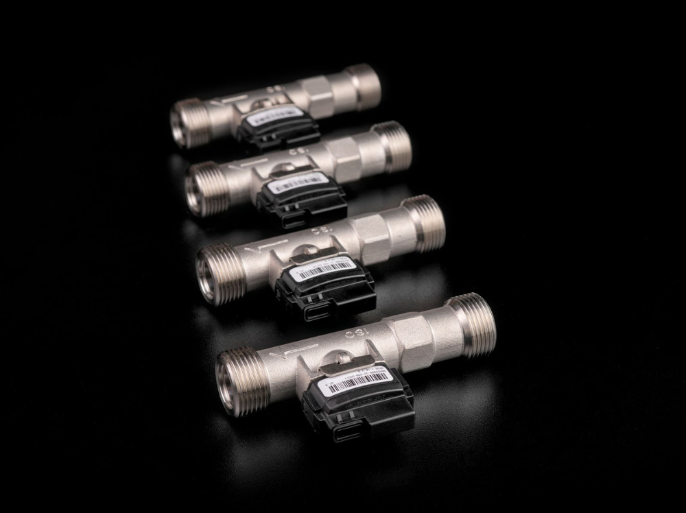
Pipe fittings
The quick connectors and fittings used for the measurements were provided by Meusburger Hungary Kft. (Table 2).
Table 2. Meusburger type water connectors used for measurements

Experiment plan/presentation
Establishment of measurement chain
During the measurement, the two tempering devices were equipped with identical measuring system, which monitored the data of mould side water circuits. The sensor is part of the system and it is installed after an 850 mm long pipe section. On the end of a 400 mm long pipe section were installed the quick connectors and throttle valve. In the experiments we tested the different types of quick connector’s effect on the flow, so only these were changed in the measurement arrangement (Figure 1). We worked with two quick connector families with different diameters (9 and 13 mm), and in the measurement we changed the diameter of the pipes together with all the connectors. The type of the used water connectors did not change, only their size.

Figure 1. Establishment of measurement chain
During the tests we examined the maximum flow rate and pressure values according to the different connection methods and fittings (Table 3). We performed measurements starting with most simple hose nozzle design to the shut-off hose couplers. The most simple way to describe the characteristic of the pumping capacity of a tempering unit is with the measured pressure values in function of flow. To record the flow curve, we used a valve, which reduced the cross-section of the flow. By gradually closing the valve, we obtain the pressure of the flowing water in the system by a given flow rate.
Table 3. Used arrangements during the measurement

Measurement results
The effect of different pipe diameters to pump characteristics
First we examined the effect of different pipe diameter to the flow and pressure values in case of the “A” tempering device. We used hoses and fittings of 9 mm and 13 mm diameter. There were significant differences in the obtained flow characteristics. (Figure 2.).
Connecting the inlet and outlet pipe stub, without throttle when using the pipe of 13 mm diameter the flow rate was larger by nearly 40% than when we used the 9 mm long pipe. With increasing pressure the differences in flow rates measured with pipes of different sizes are decreasing. At low pressure (1,6 bar) using the 13 mm pipe we measured flow rate of 16,25 l/min, while with the 9 mm pipe it was 9,5 l/min. This is a more than 40% decrease caused by pipe diameter. With increasing pressure (1,9 bar) the difference decreased, in case of the 13 mm pipe the measured value was 9,75 l/min, while 6,75 l/min by the 9 mm pipe, this means only a 30% difference. At the same tempering environment and a mould with large permeability by changing pipe fittings and hoses there will be larger differences in the flow than at a cooling system with a small permeability.
When comparing the pipes with different inner diameter it was measured that because of the bigger cross-section smaller pressure loss occurred in the 13 mm diameter pipe. At the same pipe length, in the 13 mm system without throttle a pressure of 1,55 bar was measured, and 1,24 bar while using the 9 mm fittings. This means 25% drop in pressure, which the cooling circuit of the mould might increase further. Therefore, choosing a pipe diameter can influence not only the efficiency of the cooling of the mould, but the lifespan of the tempering device and its energy need.

Figure 2. Characteristics at different tempering devices and pipe sizes
The characteristics of two, seemingly identical tempering device in different conditions were compared using both the 9 mm and the 13 mm pipe. We experienced significant differences between the two devices (Figure 2.).
In first phase of the measurement, we compared the pumping capacity of the devices without throttle using the 9 mm then the 13 mm diameter pipe. The “B” tempering device was able to produce 5 % higher flow rate for both pipe sizes compared to “A” device. In the whole range the “B” tempering device was able to build up 15-20% more pressure. Therefore the continuous monitoring of the conditions of the tempering devices is important, and by measuring the change in the characteristics regularly we will be able to tell if the condition of the tempering device is drastically decreasing. Furthermore, with control system because of the different flow values it can be immediately detected if the tempering devices were interchanged, by that preventing uncertain production process and the manufacture of faulty products.
When using the 9 mm diameter pipe, at 1,4 bar pressure in “B” tempering device the flow rate of 13,5 l/min was formed while at the same pressure in the “A” device it was 11,25 l/min. The difference between the flow rate of the two tempering device is 17% at same pressure and pipe diameter. Increasing pressure to 2 bar, this difference increased to 37,5%. The “B” tempering device had a flow rate of 10 l/min, the other created 6,75 l/min flow rate.
In case of the 13 mm hose, at 1,7 bar pressure the “B” tempering device ensured 25% more flow than “A”. Therefore, on the weaker tempering device 14 l/min flow rate was measured while on the device in better condition it was 18,5 l/min. Increasing the throttle, at 2 bar pressure the difference increased to 61,5%. The “A” tempering device ensured a flow rate of 8 l/min, while the “B” delivered 13 l/min of liquid, which can entirely change the heat balance of the mould. With increased pressure the differences between the tempering devices become more prominent. Examining two seemingly identical tempering device regardless of the pipe diameter one is able to deliver 40 % more water than this other under the same amount of time.
If in a mould with complex and small diameter cooling circuits the flow of the liquid requires more work, the differences between the tempering devices are increasing. In these cases, even more important to use a tempering device in the right condition.
Effect of the connected fittings
There can be significant differences between the connecting possibilities of the pipes with different sizes and design. We examined these at diameter of 9 mm (table 4) and 13 mm (table 5). We compared the most simple hose nozzles and quick connectors based on the water flow and pressure built up in front of them. Swapping the fittings did not cause a significant change in the ratio of the pump characteristics, therefore we compare the flow and pressure values only without throttle.
Table 4. Measurement results of the 9 mm fittings
|
Case |
Flow rate |
Decrease of flow rate |
Pressure |
Pressure change |
|
Reducing fitting |
12,71 |
100% |
1,24 |
100% |
|
Hose nozzle |
11,82 |
93% |
1,30 |
105% |
|
Open hose coupler |
9,40 |
74% |
1,59 |
128% |
|
Shut-off hose coupler |
6,00 |
47% |
2,17 |
175% |
|
The scatter of results were 0,02 bar and 0,1 l/min. |
||||
In case of the 13 mm hose without the use of quick connectors the flow rate is 17,73 l/min. The use of open hose coupler minimally reduced the achievable flow rate, the pressure value changed within the scatter field. The application of shut-off hose coupler makes simple to close automatically the not used water circuits and to prevent leakage but reduces the flow rate by 20% (Figure 4). If there is a faulty connection (self-locking and not self-locking parts), the achievable flow rate will decrease further, even to 76% of the original value without the quick connectors.

Figure 3. Comparison of the 9 mm fitting
With the use of the fittings of smaller (9 mm) diameter the flow limiting effect of the quick connectors are more significant than at the 13 mm fittings (Figure 3). When using shut-off hose coupler the measured difference is 20% at the 13 mm pipes, and 26% at the 9 mm fittings. A faulty connection (open hose coupler shut-off connector) can result in a 50% less flow in a 9 mm system, which can cause even a 75% change in pressure.
Table 5. Results measured with 13 mm fittings
|
Case |
Flow rate |
Decrease of flow rate |
Pressure |
Pressure change |
|
Reducing fitting |
17,73 |
100% |
1,56 |
100% |
|
Hose nozzle |
17,53 |
99% |
1,53 |
98% |
|
Open hose coupler |
14,25 |
80% |
1,69 |
108% |
|
Shut-off hose coupler |
13,51 |
76% |
1,73 |
110% |
|
The scatter of results were 0,02 bar and 0,1 l/min. |
||||
Regardless of size the hose coupler reduced the flow the least, while the wrongly used quick connectors had the biggest effect on the system. Important to mention that a wrongly connected 9 mm fitting can reduce the flow rate to half.

Figure 4. Comparison of the 13 mm fittings
Summary
Summarizing the results, two tempering devices of the same type is not capable to the same water delivery and temperature control, which can change the technology entirely. To reach the right flow rate, it is essential to choose the pipe with the right diameter. When using the 13 mm and 9 mm pipes the difference between the measured flow values was around 40%.
Besides the diameter, it is important to apply suitable fittings, because of their significant effect on the flow rate. With self-locking fittings a flow reduction of 3 l/min was observed at both diameters. This decrease was 20 % in case of the 13 m fittings, while 26% at 9 mm.
It describes the complexity of tempering, that it is not enough to choose the ideal of everything, but they must be used properly. In case of faulty connections (open hose coupler with shut-off connector) significant loss occurs, which can result in some cases more than 50% of flow rate reduction. At production start the time and attention of the machine setters are limited, the tempering errors are hard to detect before the production start. The Cavity Eye water measurement system is able to detect immediately the differences, therefore preventing the improper start of production or the manufacture of the faulty products.
Csaba Csipke
Cavity Eye Hungary Kft - Project engineer