Why is it important to choose the right measurement position?
-
About the company
Our customer is a Japan centered global company working in the energy sector and automotive industry with more than 75 years of experience. Part of its profile are electrical connector, cable production, power distribution and control products, screens, and sensors. Their 45 companies with more than 240.000 employees are present in 45 countries.
The project introduced here was implemented in the Portugal plant, which is a supplier of electrical connectors for the automotive industry. The company has about 200 injection moulding machines in Europe and produces around 500 million products per year.
Prior to our cooperation they did not actively used pressure measuring system for injection moulding process control. From our company they expected to get help in this area and to improve their processes.
-
Goal
The main goal of our customer was to find, identify and avert difficulties and errors experienced during production, and to improve the processes. Major point was to reduce the number of complaint due short shot, which could happen to any injection moulded part and most common causes of complaints. Ceasing these problems is one of the key factors to improve the efficiency of the injection moulding process and it brings the most visible result.
Because of the large number of products, the manual separation was proven to be expensive and not very efficient solution for the quality problems arised in every month.
They realised that they need to make such changes on both process and organisation level, which help them to improve their efficiency and output.
-
Challenge
To reach these goals, we had to determine from the customer’s five most problematic moulds the one where the most loss happens and which causes the most difficulties, and we integrated our pressure measurement system into that mould. The very first step was to identify the losses during production and to define the categories:
- Variable cycle time
- Cost to repair insert breakage
- Cost of customer complaint
- Time of hot runner balance optimalisation
- Cost of manual separation
- Daily changes in technology settings
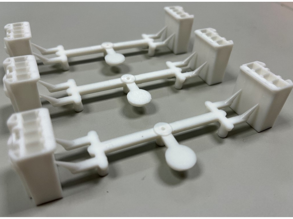
With the chosen mould four-pole connector is produced with 16 cavities at about 150.000 cycles. The mould cavity is divided at several places, has lots of inserts. To be able to choose the right measuring position, we redesigned some parts of the tool so we can measure the pressure at different locations in the cavity. Our goal was to be able to put one sensor in several measuring position and choose the most suitable one during trials. For the measurement we used the existing ejector pins in the mould.

1. figure Incomplete (left) and good product (right)
-
Solution
Into every cavity of the chosen mould we installed a sensor, but we made universal sensor pocket for each cavity. The sensors can be easily moved to different positions in the clamping plate, therefore the same sensor can be used with more ejectors pin, so the measuring position can be freely moved during trials.
It is especially important to choose the right measuring position in case of a mould with lot of inserts, because the air and subsidence from the melt (steam, gas) leave through the venting channels or the fitting gaps especially at the end of the flow. If we choose the ejector pin at the end of flow path for the measurement, the contamination between the ejector and insert can limit the free movement of the ejector pin. The other phenomenon experienced at moulds with many inserts is the closing force and the deformation of the inserts. It happens in a lot of cases that after closing the mould with clamping force, it can block the free movement of the ejector. Especially critical at the ejector pins near the contacting inserts. In this case the refitting of the ejectors / inserts, other measuring position could be the solution. If the ejector gets stuck and the measurement is not right, the phenomenon can be easily identified during production or even before that in the tool shop.

2. figure Measuring position (left) and clamping plate design (right)
From 4 possible measuring position shown on figure 2., we choose the one marked with red, where we built in the sensor and then installed the measuring system to the machine. We checked during trial if the ejector and transfer pins are working well and if the cavity pressure measurement functions properly.
The next step of the solution process was the technology optimalisation, which was achieved by the following steps:
1. We started the production with the parameters last approved by the customer to have baseline data
2. Without holding pressure we optimised the filling speed with visual inspection of the product
3. With the help of the new injection profile we set hot runner balance
4. We set two-step filling process which resulted in near the same switchover and holding pressure value
5. We optimised the holding pressure and time
6. We set the process window and checked the part separation
The two-step filling process consist of a high-speed, fast filling (90%) and a slower controlled pressure building phases. Its advantage is that the injection moulding machine carries out the process in a well-controlled way regardless of changes in material properties.
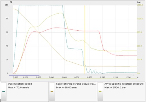
3. figure Two-step filling process
During optimalisation compared to the original settings (red pressure curve) we increased the filling rate and when the part was 90% filled we decreased the injection speed to a fifth in one step. Thanks to that there were only 100 bar difference between the pressure measured at switchover and the holding pressure instead of the earlier 500 bar. This resulted in a more stable process and lesser chance to screw back movement.
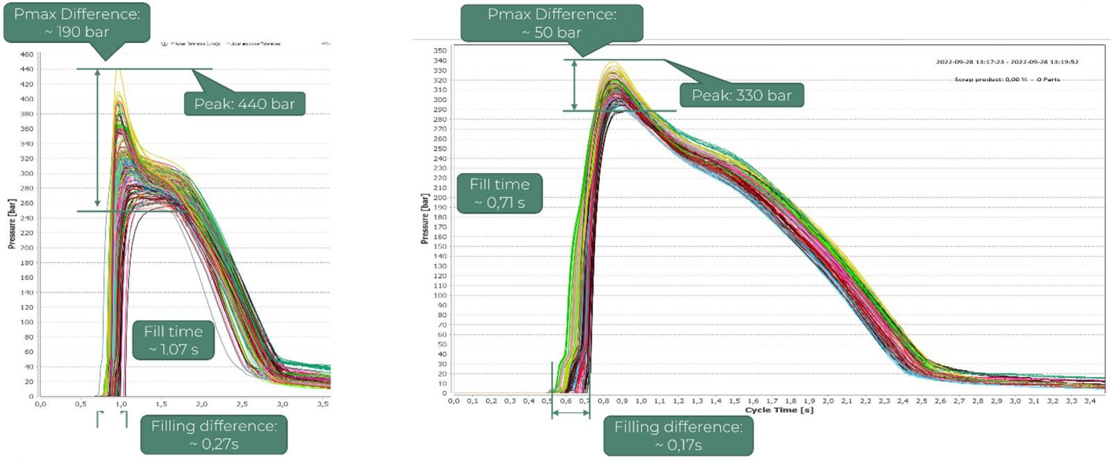
4. figure Pressure curves before (left) and after (right) technologization
-
Results
Thanks to the Cavity Eye system we successfully set the cavity balance and smallest deviation possible between the cavities. The automatic separation of bad and good parts was achieved which resulted in no more customer complaint. We could also show the differences between the hot runner and gates, optimised the holding pressure and time.

The return of investment of the system can be considered less than one month, and the improvements can be seen in many areas. The biggest saving is the monthly cost of several thousand euros of manual sorting and complaints. The drastic decrease in the number of insert breakage adds to the reduction of direct and indirect costs. Reducing the cycle time by 5 seconds brings plus 100 working hours monthly. Decreasing the time requirement for the optimalisation of hot runner and holding pressure significantly improved efficiency.
An injection moulding company had problems, difficulties and wanted to improve. And we could give them the solution which helped to find the mould-side problems and avoid leaving faulty products between the good ones.