Measurement with thermal imager – Mould temperature
Introduction
The infrared image is a radiation-based temperature measurement method.
The electromagnetic radiation emitted by the bodies depends on:
- Material temperature,
- Body material,
- Surface quality
The ideal emitter is the “absolute blackbody”.
The radiation emission capacity of the non-blackbody, namely the emission factor (ε) (regardless of wavelength interval) is always smaller than 1.
Three factors determine the radiation of the surface:
- Emission: radiation emission ability, describes emission factor (ε)
- Reflection: radiation reflection ability, describes reflection factor (ρ)
- Transmission: radiation transmission ability, describes transmission factor (τ)
The sum of the three factors gives the total intensity of body on every wavelength:
ε + ρ + τ = 1
In practice the transmission (τ) is small at most material, τ ≈ 0,
so: ε + ρ = 1
Therefore:
High emission ⇒ low reflection,
High reflection ⇒ low emission
The goal of the measurement is to show how each change of settings effects the measuring results
Preparation and steps of the measurement
We place the standing side of the mould on a table and connect the tempering device.
We set the tempering device to 50°C and wait till the mould warms up.
With touch thermocouple we measure the surface temperature, which will be considered as a reference. In our case this value is 40,5°C.
The measurements are performed from three different distances at four different ε (emission factor) values to find the most appropriate setting.
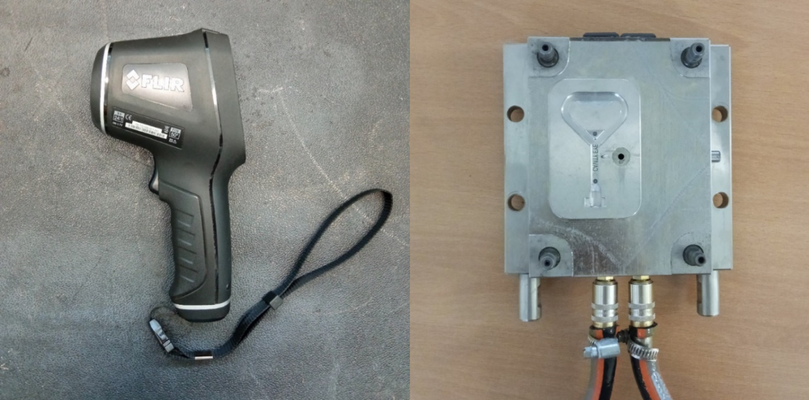
Figure 1. Thermal imager and tempered mould used for measurement
Perform measurement
3 different distances: 25 cm
50 cm
100 cm
At 3 different angles: 30°; 60°; 90°

Figure 2 Arrangement of the measurement
4 different emission factor (ε) settings: 0,30; 0,60; 0,80; 0,95
During measurement always try to measure the same point.
It is worth to repeat the measurement here too to exclude the measurement inaccuracy.

Figure 3. Picture of thermal imager
Results
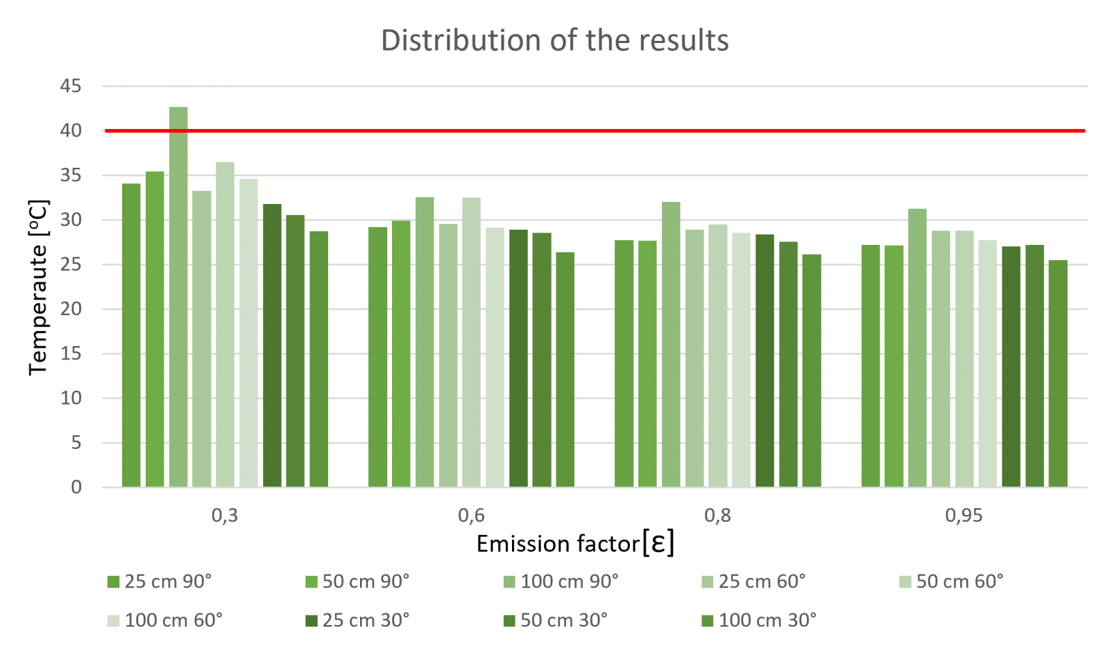
Conclusion
The cavity plate has high reflection, so at low emission factor (ε=0,3) could we get the results near the set temperature.
We got the highest values mostly at 90°, and the lowest at incidence angle of 30°.
The closest result to the reference temperature was at the setting of 0,3 emission factor, from 100 cm distance while the thermal imager held at 90°. This average value was 42,7 oC.