During the production of injection molded products, one of the most important and in terms of cycle, also the longest part is the cooling process. Fundamentally determines the quality of final product and efficiency of the production (cycle time). Usually, two methods are used to get control of tempering:
- Measuring the mold temperature (surface or cavity thermocouple, infra sensor etc.)
- Monitoring the conditions of the medium used for tempering (temperature, pressure, flow)
The benefit of the second method is that there is no need to modify the mold, and after installing the measuring equipment onto the machine, more than one mold can be used at the same injection machine. To control the whole injection cycle including the cooling phase, it is necessary to measure the temperature, pressure and the volume of the tempering liquid. by this way the continuous product quality can be ensured, and possible to reach a higher level of technology which can open doors to manufacture new products with higher requirement (quality, quantity). The Cavity Eye Hungary Kft. – besides the cavity pressure measurement – offers a fully integrated solution with their newly developed Water Flow Monitoring product to monitor and control the tempering process. The internal pressure and tempering control solutions together give reliable information to ensure the continuous product quality and production process monitoring.
The first and mandatory step of production launch is to fasten the water hoses to the mold according to the cooling plan. The appropriately and consistently connected water circuits can ensure that the heat removal is theoretically identical and constant. In practice many errors can occur in everyday production life due to equipment, maintenance or connecting errors.
Tempering device
It may often be forgotten that there could be large differences between two seemingly identical tempering devices. Over time, the equipment loses transport capacity leading to considerable variation in the pressure-flow characteristics. Continuous equipment monitoring helps to make decisions by data not by feelings.
Mold maintenance
Deposit or contamination can appear from the flowing medium (mainly water) in the mold cooling circuits. These could reduce the flowing cross-section and have insulating effect, decreasing the amount of extracted heat. If the flow rate decreases, laminar flow may develop, which greatly reduces the amount of extracted heat leading to significant rise in the mold temperature. Not to mention the sliders, where the circuits have small cross-section, if at least a 2l/min flow cannot be achieved, then the metal surface of the slider may overheat. With regular inspection of the cooling circuits condition in the tool shop – before placing the tool onto the machine – lot of time and energy can be saved, the measured data can be stored and retrieved furthermore the maintenance can be planned. This will help to avoid failed production launch, scrap and customer complaints.
Water connection failures
The water circuits are mostly connected directly through tempering device or through distribution (rotameter, manifold). A single mold cooling circuit can be connected to the system in two ways. In the case of a parallel connection the tempering device cannot detect if a circuit becomes clogged or a hose slips out. With serial connection the tempering unit can detect the fault, but the flow rate drastically decreases and there will be a large temperature difference (in some cases 10-15°C) between the inlet and outlet. This can cause inadequate products due to the different cooling rate among the cavities. If the hose breaks at closing or its length changes, the flow rate may fluctuate. If the inlet and the outlet circuits are reversed, totally different shrinkage and warping may occur on the product. The best solution is to measure the flow rate, temperature and pressure of the supply and return cooling circuits, thus the tempering errors can be recognized immediately. The system makes it possible to determine the reference and tolerance values for several cooling circuits per mold (technological process). Warning and intervention levels can be defined for the alert system therefore the notifications will reach the right person at the right time. The system can even stop the machine preventing the production of scrap parts.
Cavity Eye Flow control system
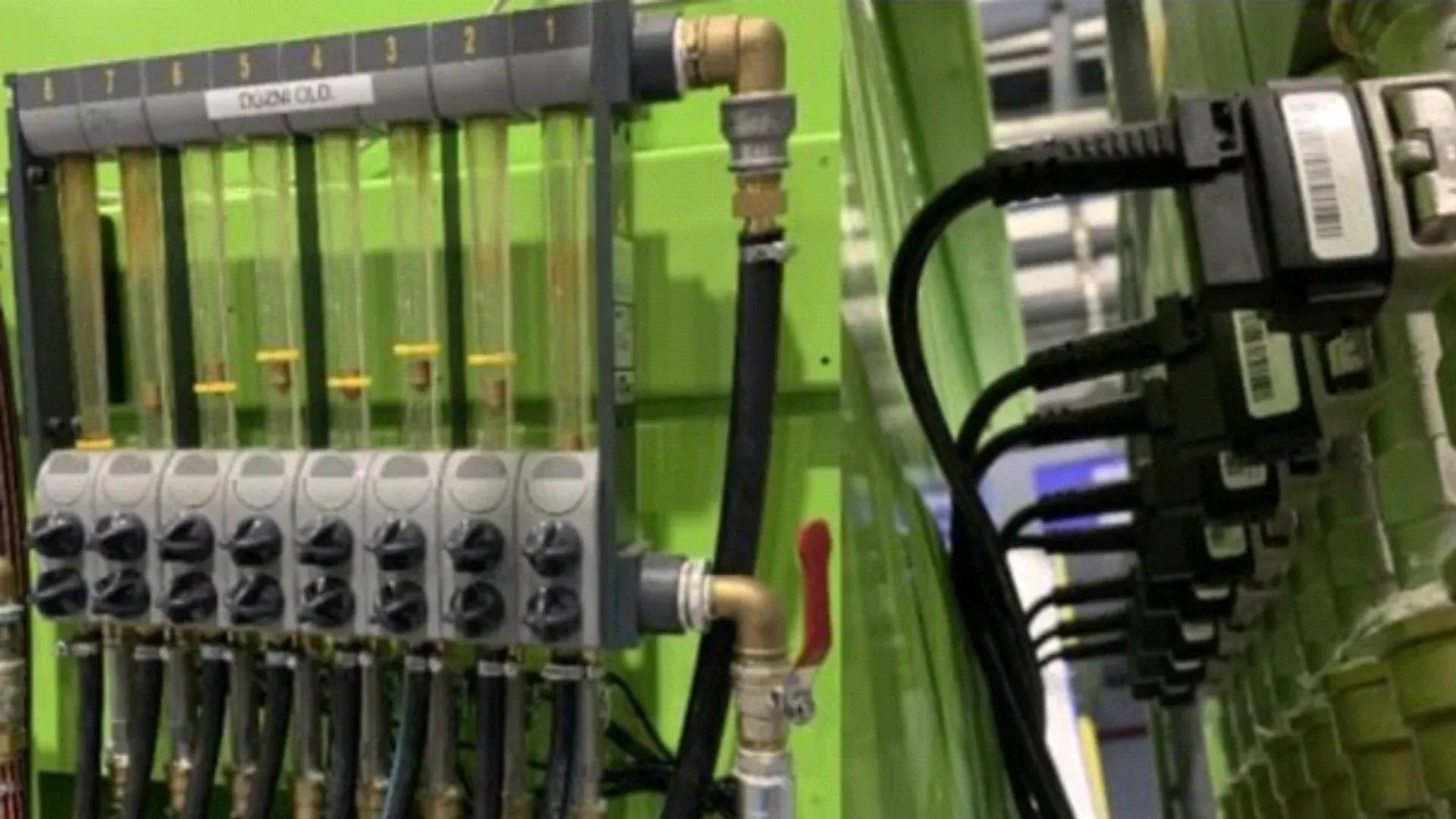
The two most common applications of the system are the manifold and the independent pipe solution. Cavity eye’s own developed manifold is available with 4 or 8 channel version (Figure 1.), which usually placed in the mold clamping unit, but if there is not enough space (<50 t injection molding machines) the measurement is located outside the clamping unit. The pipe solution makes possible to choose the sensor’s locations freely. It can be placed around the clamping unit, or onto an existing manifold. The sensors can be put even into the rotameter or directly to the inlet or outlet of tempering device. Depending on the design, the sensors are capable to measure three physical quantities: flow rate [l/min], temperature [°C] and pressure [bar]. From the temperature difference between the supply and return water circuit, with a known flow rate, the extracted energy can be accurately calculated. This makes it possible to monitor the process variations, plan the preventive maintenance and to follow the condition of tempering device. By monitoring the sudden pressure drop a slipped fitting or a broken hose can be quickly detected, and the tempering device can be stopped.
By connecting the Cavity Eye Flow system to the network, the production data can be collected on a central server and can be easily analyzed. The data from the cavity pressure and waterflow measurement can be collected at the same place and correlating the data sources together, the process oversight and traceability can be raised to the next level.
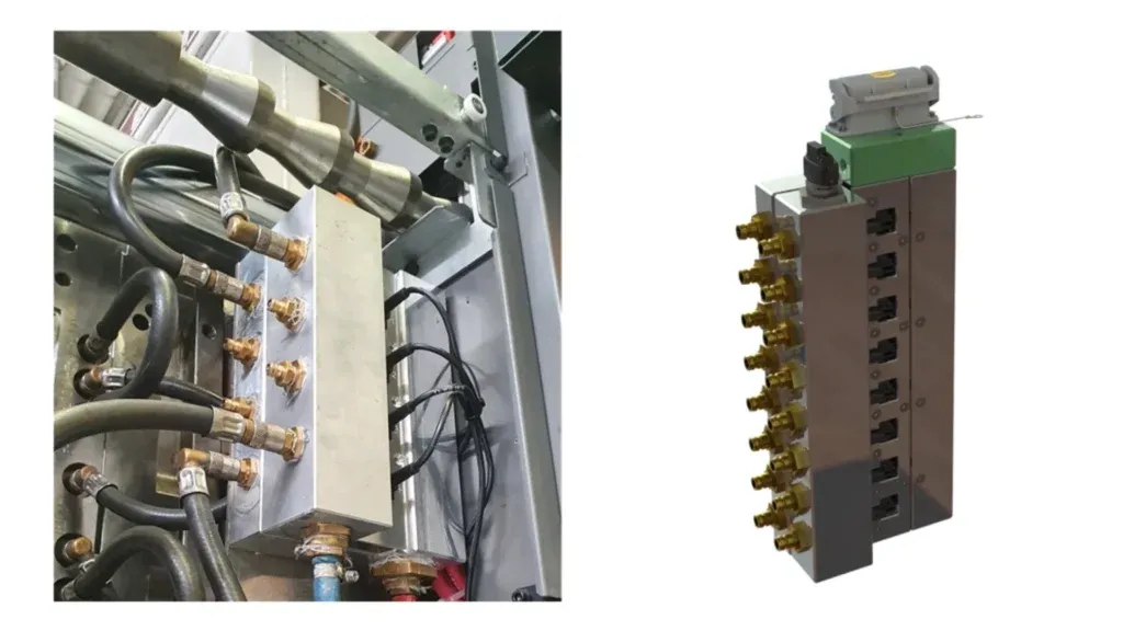
Figure 1. Cavity Eye manifold with 4 and 8 channels
Industrial tests and experiences
When the water circuits are connected to the installed measuring system, a water connection plan should be prepared for each monitored circuit. This way the chance for typical errors (misconnecting the hoses) can be significantly reduced. It is necessary to define the reference values for the flow rate, pressure and temperature. This can be achieved in one step but only after the thermal equilibrium state is reached inside the mold. The data collection is continuous, and a sample is taken every second. The monitoring system can be switched on and off manually or automatically at production launch.
By analyzing the measured data, the tempering errors can be identified. After mold maintenance, it happens often that the hoses are not put to the same position as previously (Figure 2.) If the pipe diameter or the condition (fastener diameter, pipe length) has changed, it can drastically affect the waterflow. It results in a significant change in the cooling process. Similar effect happens if the supply and the drain are reversed or even connected to other positions of the mold. It is common for a broken or clogged hose to cause flow loss. If the error occurs periodically (related to cycle time), the blocking of the tube is certainly caused by the mold closing and opening. If the measured values fall outside of tolerance range, the system detects it immediately, and it can prevent production start. The cooling of a product with short cycle time (4-10 s) is always critical because a significant amount of heat must be transferred quickly. If the production stops even just for a few seconds, the system can detect it and send a notification.
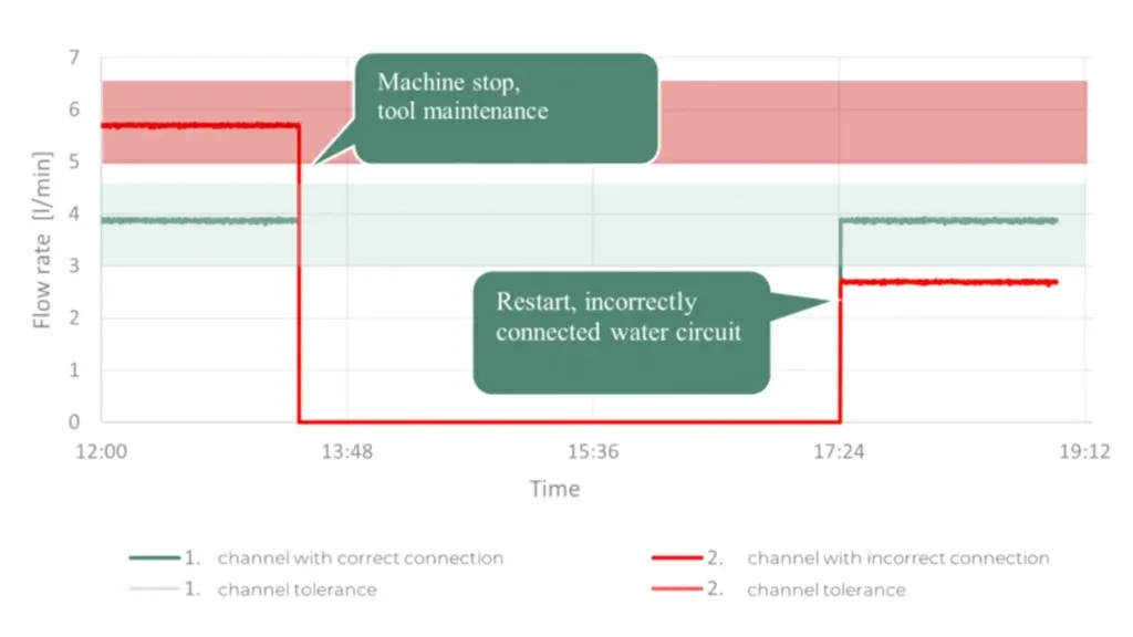
Figure 2. Tool maintenance – smaller diameter on the second channel resulted in the decrease of flow
Network-based data collection and analysis allow to monitor the conditions of the cooling circuits in the tool and determine the optimal maintenance intervals. If limescale is formed on the surface of the cooling in the tool, then the efficiency of heat transfer is reduced. Therefore, the temperature difference between the supply and return of the given circuit is decreasing, often to 2-10°C. If all circuits are affected by contamination, then this phenomenon happens similarly at all circuits. If only one circuit is polluted, then the polluted water circuit transfers less heat at the same flow rate so temperature difference decreases. The mold will heat up, so the heat must be dissipated by other circuits. As a result of this the supply and return temperatures of the nearby cooling circles will minimally increase (Figure 3.). By testing the mold before production, the number of unsuccessful production launch caused by water circuit failure can be reduced to zero. For this purpose, Cavity Eye device provides a solution.
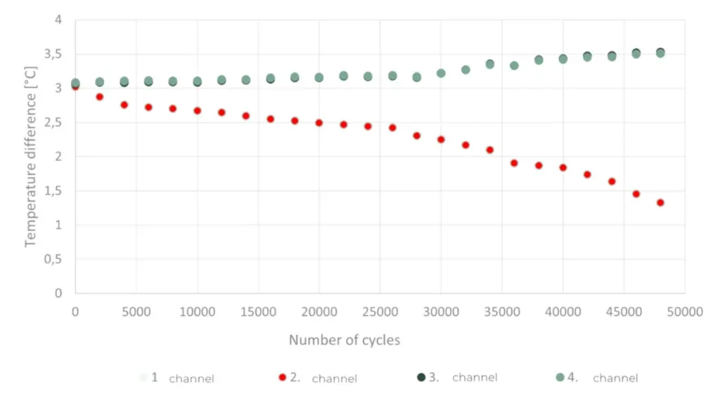
Figure 3. Analysis of 50 000 injection molding cycles – contamination of the cooling circuits is causing a decrease in the difference between the inlet and outlet temperatures
Summary
Cooling is a key part of the injection molding cycle. The more efficient and controlled the process is, the more productivity can be achieved. The controlled and increased production also helps to increase machine utilization. Often a shut-off fitting, a smaller diameter hose or a half-open tap can result in several hours of scrap product because the defect will be revealed after assembly of the product. The complex tempering of the mold can be monitored, and the constant quality of the product can be improved. Adding this system to cavity pressure measuring, scrap-free production is guaranteed, and customer complaints can be avoided.